So, we’re going to turn a low-cost Raspberry Pi Pico board (about $5) into a real programmable logic controller (PLC). And to set up the logic for our homemade PLC, you only need to know how to read electrical schematics.
We can automate things like a greenhouse, a water pump, or automatic gates — it all depends on the logic you design. The only limit is your imagination. The Raspberry Pi becomes the brain that controls everything.
What You’ll Need:
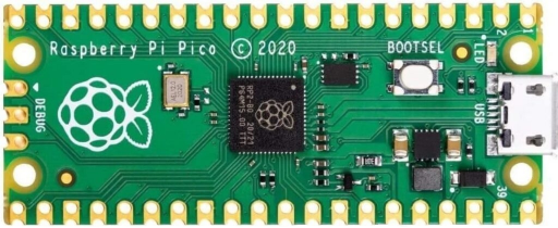
- A Raspberry Pi Pico board — you can buy it in online stores like Amazon, Ebay etc.
- Connect the board to your computer while holding the BOOTSEL button. It will appear like a USB drive, and then you can copy the firmware file onto it.
Setting Up the Logic:
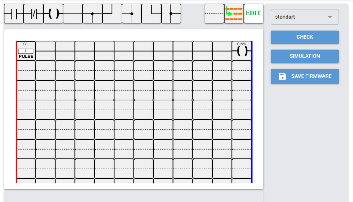
Click the button to launch the Ladder Diagramm Online Editor.
The program editing page will open, as shown in Fig. 2 below.
- In Ladder Diagramm Editor Online , you draw your electrical schematic using ladder diagrams — these diagrams look like relay-based control circuits, with contacts and coils.
- The logic you draw in the diagram becomes the “program” that runs on the Raspberry Pi. Upload it to the microcontroller — done!
- In the example shown in Figure 2, pulses from the pulse generator G1 are sent to the LED built into the board (connected to GP25) and will light up and go out once per second.
Technical Details:
- The programming uses the Ladder Diagram (LD) language, which is part of the IEC 61131-3 standard.
- This language is designed for electrical engineers who may not know languages like C, C++, or Python — but who can read electrical schematics.
- LD is used by well-known PLC manufacturers like: Siemens, Schneider, Omron, Allen-Bradley, and Mitsubishi.
How to Work With LD Editor online:
- There is a short video , that shows how to use Ladder Diagramm Editor.
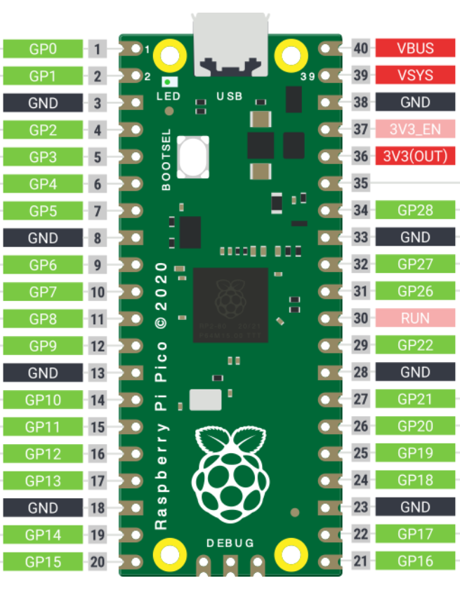
- You should use the pins marked from GP0 to GP28 (highlighted in green in the diagram). But note: GP25 is used by the built-in LED.
- In the ladder diagram, if a Pico pin is defined as an input (normally open or normally closed contact), that input is considered active when 3.3 V is applied from the 3V3 (OUT) pin.
More information about the online service can be found on the detailed documentation page.
Interfase description is here