While studying the RP2040 microcontroller architecture, I developed an adapter for analyzing the CAN protocol. I’d like to share instructions for building one myself.
The device is connected to the computer via USB, the CAN adapter input is connected to the CAN_H and CAN_L conductors of the bus being analyzed.
The CAN data transfer protocol is widely used in transport, industry, and other sectors. I won’t go into detail, but since you’ve landed on this page of my website, you know perfectly well where you’ll be using the adapter.
The CAN adapter allows you to monitor what information is transmitted via the CAN bus, as well as transmit CAN packets; speeds of 125, 250, and 500 kbps are supported.
A distinctive advantage of the device is its ease of manufacture and low cost of components.
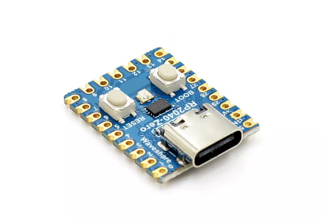
To build it you will need an RP2040-Zero board, which costs around $3.
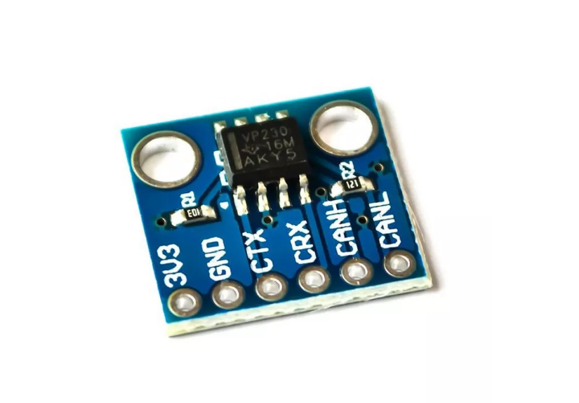
And the CAN bus transceiver module WCMCU-230, based on the SN65HVD230 microcircuit, the price is about 2 US dollars.
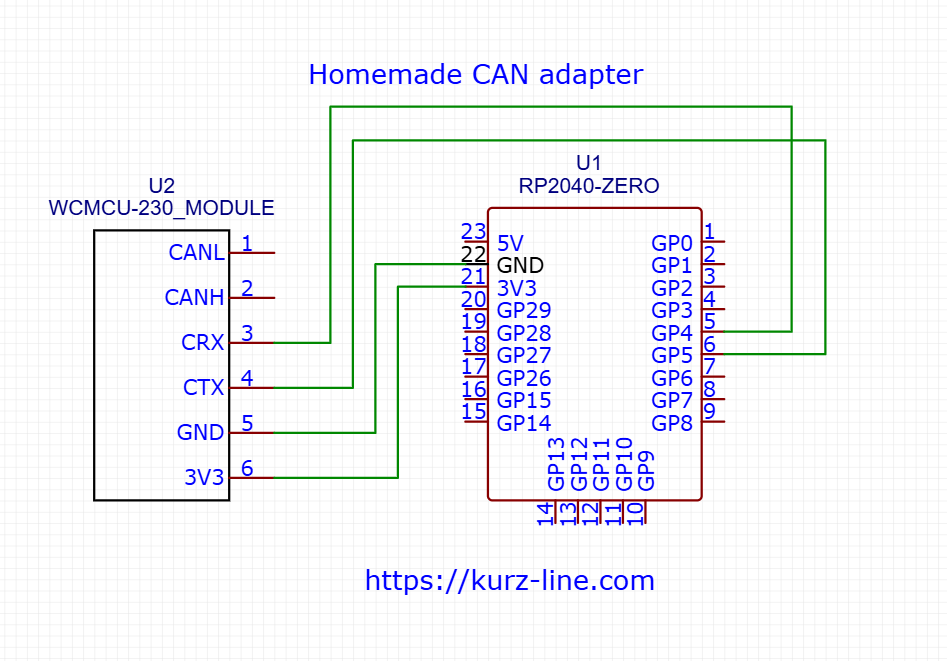
The boards are connected to each other by 4 wires according to the diagram.
For additional rigidity, I secured the modules to a breadboard and installed a quick-release connector. The result was a matchbox-sized structure like this.
You can purchase the components necessary for production at any online store.
To download the firmware, click the button below:
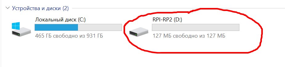
To flash the board, you don’t need a programmer. To flash the RP2040-Zero, press and hold the boot button and connect the board to the computer. The device will be detected as a USB drive, and all you have to do is upload the downloaded firmware file with the uf2 extension.
To work with the device, you can use any program for working with a serial port, for example: CoolTerm, putty, QCOM, MobaXterm and others, there are many analogs on the network, I use the QCOM program from Qectel, it is convenient because you can pre-register the commands to be sent.
In the program settings, select the serial port the CAN adapter has detected on your computer. Set the serial port baud rate to 115200.
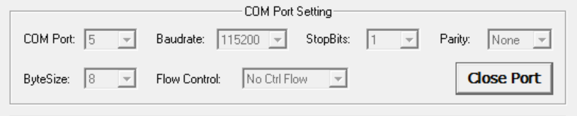
Please note, the port number on your computer may be different! You can find it in the Device Manager.
The device transmits and receives commands in JSON format. When a command is received, the on-board LED flashes red, and when a command is transmitted, it flashes green.The format for a received CAN data packet is:
{
    "command":2,
    "can_id":"0x1ff",
    "dlc":8,"
     data":["0x01","0x02","0x03","0x04","0x05","0x06","0x07","0x08"]
}
Where:
command–the type of the executed command (when receiving message, it is equal to 2)
dlc – length in bytes
can_id – packet address
data – data.
To transmit a CAN data packet, the command field
must be set to 1; this is how the device understands that the packet should be transmitted. The transmitted command must be written on a single line and must not contain line breaks within the curly braces.
After enabling, the CAN adapter operates at a default speed of 125 kbps. To set the exchange rate according to your parameters, you need to send a command of the following format to the device:
{"command":3 , "speed":500} The speed parameter
is the data exchange speed on the CAN bus and can take values of 125, 250, 500 (kbps).