The Ladder Diagramm editor program has a classical interface that is easy to learn and is adapted for work not only from a personal computer but also from touch devices such as tablets.
Let us consider the interface elements of the program.
At the very top of the window there is a title bar. To the right of it there is a link to the documentation and the MENU buttons.
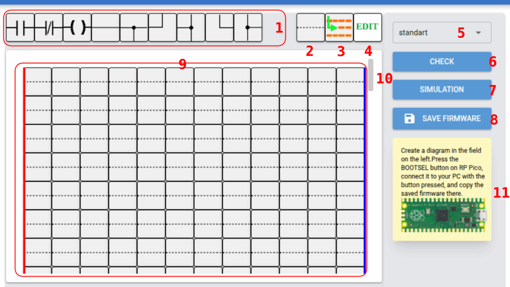
Under the menu bar there is the ladder diagram component selection panel (1) in Fig. 1.
By clicking the left mouse button on the required component, it is selected and becomes the current one.
A subsequent left mouse click on the workspace (9) will insert the selected component into the workspace.
If it is necessary to insert several identical components, the insertion operation of the current component can be repeated multiple times.
There are two sets of components.
In the first set (standart) the most frequently used LD language components are concentrated:
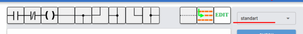
normally open contact
normally closed contact
coil,
connecting lines
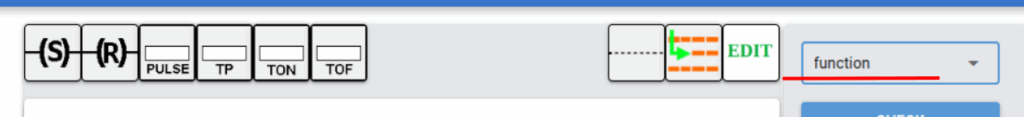
In the second set (function) the less frequently used components are concentrated:
RS trigger
counter,
pulse generator,
timers.
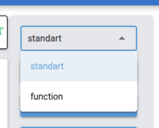
Switching between the required sets of components is performed by selecting the corresponding set in the drop-down list located on the right side of the program window (5) in Fig. 1; in expanded form this same element is shown in Fig. 2.
Under the component selection panel there is the workspace (9) in Fig. 1 and the scroll bar (10).
The workspace is the main interface element of the program with which the user interacts.
The workspace is used for building ladder diagrams; it also displays the names of inputs, outputs, coils, and the parameters of other ladder diagram elements.
During ladder diagram simulation, the current state of the elements is displayed in the workspace.
When checking the correctness of the ladder diagram construction, errors are displayed.
On the right edge of the workspace there is a scroll bar.
As a rule, a ladder diagram occupies a large number of rows that do not fit in the program window.
The scroll bar simplifies navigation through the ladder diagram.
To move the ladder diagram, it is necessary to click the left mouse button on the scroll bar slider and drag it in the required direction.
Some browsers hide the scroll bar; in order for it to appear, move the mouse cursor to the workspace area.
To the right of the workspace there is the CHECK button (number 6 in Fig. 1) for checking the constructed diagram for errors.
When this button is pressed, the correctness of the constructed diagram is checked, and if errors are present, the components containing errors are highlighted in red.
The simulation start button (7) SIMULATION.
When pressed, the simulation mode of the constructed ladder diagram is started and its operation is visualized.
This mode allows analyzing the operation of the ladder diagram without loading it into a real controller and finding existing logical errors.
This mode is also very convenient for teaching students, since it allows visually observing the operation of the controller program.
Button (8 in Fig. 1) SAVE FIRMWARE is intended for saving the firmware to the local disk of your computer or directly to the memory of the Raspberry Pi Pico microcontroller.
Let us return to the window title.
It contains a link to the documentation (12) in Fig. 4 and the program menu display button (13) in the form of three horizontal lines.
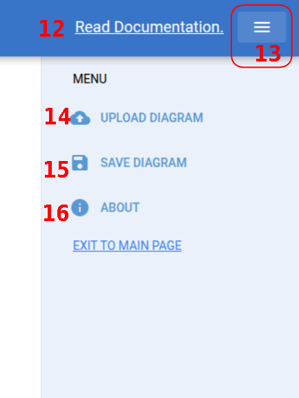
When button (13) is pressed, the program menu containing the following items is displayed on the screen:
UPLOAD DIAGRAMM — loading a ladder diagram file from disk (14) in Fig. 3.
When this item is selected, a standard file open dialog window opens, in which the user will be prompted to select the folder containing the ladder diagram file.
After selecting the file, the ladder diagram contained in it is displayed in the workspace.
SAVE DIAGRAMM — saving the ladder diagram displayed in the workspace to the hard disk of the computer.
In the opened standard file save dialog window, the user will be prompted to select the save directory and the file name.
By default, files are saved in XML format.
About — when the About item is selected, a pop-up window opens with information about the program and the libraries used.
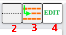
Buttons 2, 3, 4 in Fig. 1/3 are displayed on all component palettes and contain elements necessary for editing the ladder diagram:
Button (2) — Filler in Fig. 3, intended to remove an incorrectly entered or unnecessary element from the ladder diagram.
Button (3) — Insert row in Fig. 3.
Button (4) — EDIT in Fig. 3.
When this button is pressed and then any component in the workspace is clicked, instead of the hint (11) in Fig. 1, input fields for changing the properties of the selected component are displayed.
Short hints describing the parameter being changed are located in the input fields.
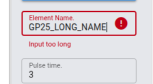
When the values of any input field are changed, their correctness is checked.
When attempting to enter incorrect parameters, the input field is colored red (Fig. 6) and a message with an error text is displayed.
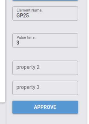
After entering or changing the parameters, it is necessary to press the APPROVE button (Fig. 5).
Creating a Ladder Diagram
A programmable logic controller is able to replace a complex and bulky circuit built on the basis of electromechanical relays.
When developing a ladder diagram, it is necessary to strive for maximum transfer of logic into the controller and to reduce the number of external relays.
It is necessary to analyze whether there is a sufficient number of inputs and outputs.
The construction of a ladder diagram is performed on the workspace (9) of the LD editor program, see Fig. 1.
The workspace is a table with a width of 12 columns and a height of 50 rows.
To select a component, it is necessary to click the left mouse button on the workspace of the component panel.
If the desired component is not present in the displayed panel, it is necessary to switch the component panels using the panel drop-down list (5), see Fig. 1.
The left terminal of components located in the leftmost column of the workspace is considered to be connected to the plus (vertical red line).
The right terminal of components located in the rightmost column of the workspace is considered to be connected to the minus (vertical blue line).
After selecting the desired component, it is necessary to click the left mouse button at the place in the workspace where the selected component must be inserted.
After inserting the component in the required place, it is automatically assigned a name reflecting the component type, the column number, and the row number of the ladder diagram into which it is inserted.
The component name is displayed above it.
In the future, the name can always be changed to the desired one.
It is necessary to carefully approach the choice of the name and try to name the component so that the name reflects the function performed by the component; otherwise, for other students or for the author of the ladder diagram after some time it will be difficult to understand its operation.
Series and parallel connection of all components is performed using connectors, the insertion algorithm of which is the same as for components.
The connectors are located in the standart set of the component panel. See Fig. 1.
There are certain requirements for component placement.
Thus, coils, including SET and RESET coils, can be placed only in the rightmost column.
All connector branches must be connected.
It is also not allowed to leave component terminals unconnected.
If these conditions are not met, the program will diagnose an error at the checking stage, and its simulation as well as loading into the programmable logic controller will be impossible.
All components placed on the workspace must have a name; at the same time, for some components the actual functionality depends on the selected name.
If the name of one or more contacts matches the name of a coil, then the contact is considered to be controlled by this coil.
SET or RESET coils with the same name are considered to belong to an RS trigger with this name.
Some components have additional input fields, see Fig. 5, that determine their characteristics.
For example, for timers this is the delay time value.
The value of this field can be any non-negative number.
The component substitution symbol insertion (2), see Fig. 4, is not part of the LD language, but it is necessary when editing a ladder diagram in a situation where it is required to delete or replace any of the elements.
It is necessary to select this component and then click on the ladder diagram element that must be deleted or replaced.
In simplified terms, it can be said that it performs the same function as the space character when typing text.