Briefly about the development board
This is a small, inexpensive, and very capable board based on the RP2040 microcontroller (from Raspberry Pi itself).
Like all Raspberry products, it has excellent documentation.
Link to the official Raspberry Pi website
There are 2 Pico families, 1 and 2.
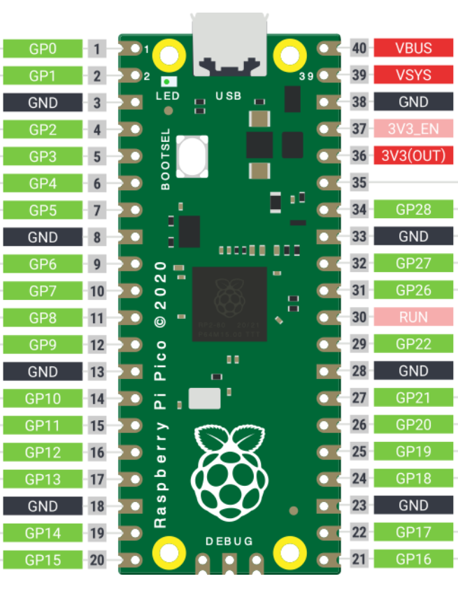
The Ladder Diagramm Editor online has so far been tested by me only with the first family (see Fig. 1).
Hardware
Processor: RP2040, 2 cores ARM Cortex-M0+ (up to 133 MHz)
Memory: 264 KB RAM
Flash: usually 2–4 MB
GPIO: 26 pins
Interfaces:
I2C
SPI
UART
PWM
ADC (3 channels)
Price: up to 5 USD, cheap and cheerful
Downloading a ladder diagram to the controller.
Flashing the firmware in .uf2 format downloaded from the service editor.kurz-line.com is extremely simple, no special adapters or programmers are required. Connecting the Raspberry Pi Pico to a computer is done via a standard USB cable. The system recognizes it as a USB mass storage device. The key requirement is to press and hold the BOOTSEL button on the board while connecting it to the computer.
Using physical pins
In order for the program to run not only in the simulator but also on the real Raspberry Pi Pico board, it is necessary to specify the names of inputs and outputs according to the way they are named by the board manufacturer in the official documentation (highlighted in green).
For the program to understand that this is a Raspberry Pi Pico board pin, it must be designated as in the left column of Table 1:
capital letters of the English alphabet followed by its number.
For example: GP22, GP0.
The use of the designations from the left column of Table 1 is allowed only for contacts and coils.
If a normally open or normally closed contact is named in this way, then the Raspberry Pi Pico pin will be configured as an input (Fig. 1, pins GP4, GP17).
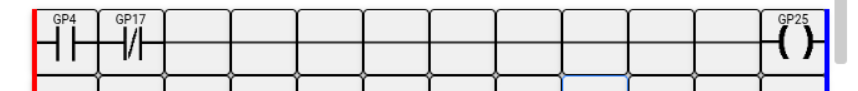
The ladder diagram logic will consider a normally open contact closed when voltage is present on the Raspberry pin with the same name, and, conversely, a normally closed contact open.Fig. 2 Example of naming RP Pico pins in a ladder diagram
If a pin name from Table 1 is assigned to a coil (GP25 in Fig. 1), then this physical pin is considered an output and can control a real load.
| Input/output port name | Use case |
| GP0 | INPUT/OUTPUT |
| GP1 | INPUT/OUTPUT |
| GP2 | INPUT/OUTPUT |
| GP2 | INPUT/OUTPUT |
| GP4 | INPUT/OUTPUT |
| GP5 | INPUT/OUTPUT |
| GP6 | INPUT/OUTPUT |
| GP7 | INPUT/OUTPUT |
| GP8 | INPUT/OUTPUT |
| GP9 | INPUT/OUTPUT |
| GP10 | INPUT/OUTPUT |
| GP11 | INPUT/OUTPUT |
| GP12 | INPUT/OUTPUT |
| GP13 | INPUT/OUTPUT |
| GP14 | INPUT/OUTPUT |
| GP15 | INPUT/OUTPUT |
| GP16 | INPUT/OUTPUT |
| GP17 | INPUT/OUTPUT |
| GP18 | INPUT/OUTPUT |
| GP19 | INPUT/OUTPUT |
| GP20 | INPUT/OUTPUT |
| GP21 | INPUT/OUTPUT |
| GP22 | INPUT/OUTPUT |
| GP25 | OUTPUT TO BUILDIN LED |
| GP26 | INPUT/OUTPUT |
| GP28 | INPUT/OUTPUT |
| GND | Ground (GND) |
| 3V3 | 3.3 V power supply |
Typical connection circuits
Connecting buttons and switches to RP Pico inputs
External buttons, toggle switches, limit switches, selectors, and similar devices must be connected from pin 36 of the Raspberry Pi board (3.3-volt output), through a resistor from 220 to 560 ohms, similarly to the circuit shown in Fig. 3, but with the number and quantity of inputs according to your program.
Resistors are required to protect the microcontroller inputs.
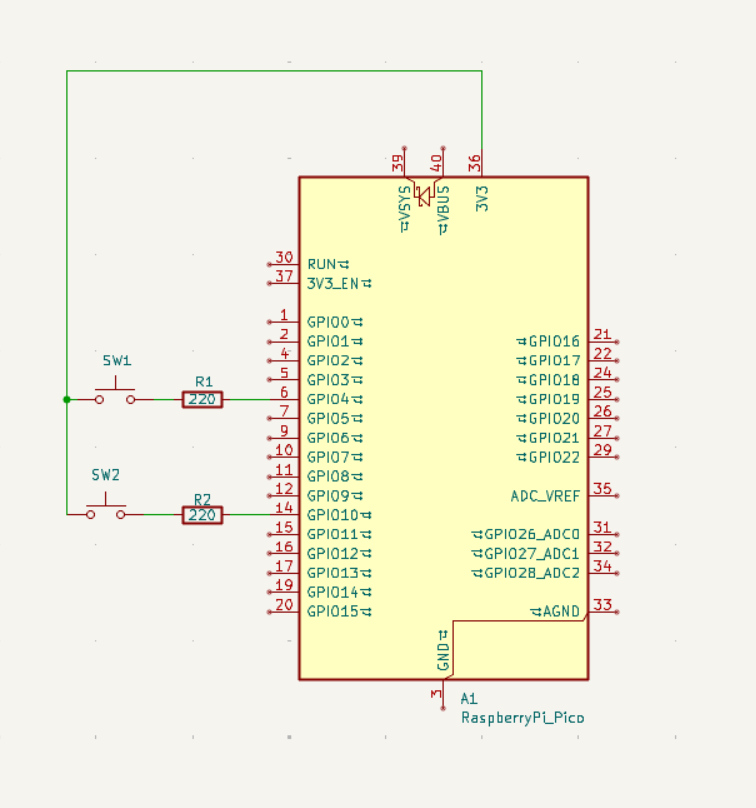
For the inputs, pull-down resistors to ground are enabled to protect against interference.Fig. 3 Example of connecting buttons to Raspberry Pi Pico
How to apply an external signal with higher voltage to an RP Pico input
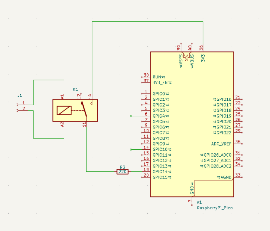
Very often, it is necessary to apply an external signal to a microcontroller input, but the inputs are designed only for voltages not exceeding 3.3 volts.
The simplest solution available to beginners is to use an intermediate relay connected similarly to the circuit in Fig. 4.
The signal is applied to the relay coil; it operates and then, by means of its contacts, applies 3.3 V to the input of the development board.
The coil of the intermediate relay must correspond to the applied voltage, for example 12 V DC, 24 V DC, or 220 V AC.
Connecting a relay module as an output to RP Pico
The simplest option is to use a relay module for Arduino similar to the one shown in the figure below.
They exist with different numbers of relays, up to 16 on one board from those I have seen.
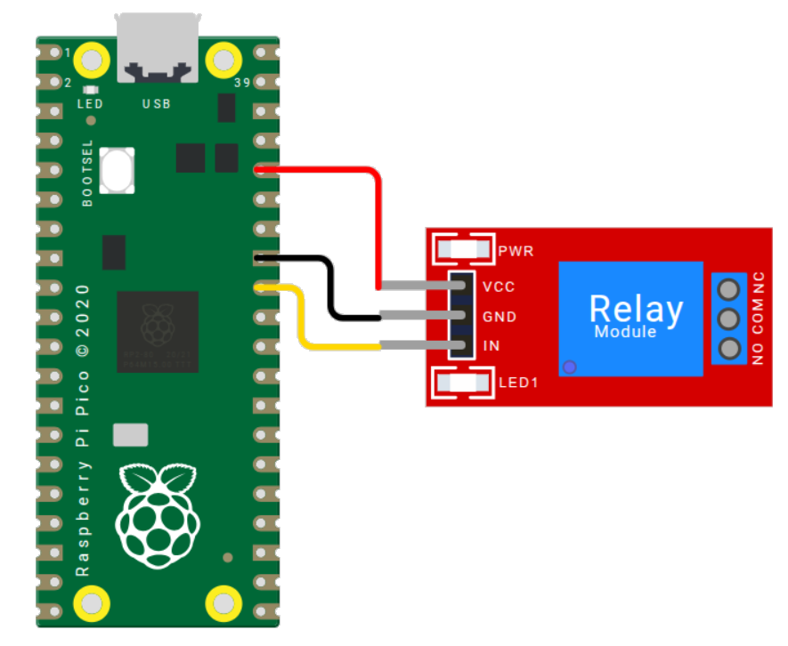
Relay VCC → Pico 3V3
Relay GND → Pico GND
Relay IN → any Pico pin from Table 1 designated in ladder diagramm as a coil –( )–
The load is connected to the relay module contacts: NO, COM, NC.
Attention: not all relay modules from all manufacturers retain operability at 3.3 volts. However, the module must be powered from 3.3 volts; otherwise, the RP Pico output may fail.