In the 1970s in the United States, production lines were mainly controlled by automation systems assembled using electromechanical relays. Such solutions had low reliability and flexibility; as a result, complex relay circuits began to be massively replaced by Programmable Logic Controllers (PLCs).
The new programmable controllers had to be serviced by the same specialists who had previously serviced relay circuits [1]. This created the need to develop a microcontroller programming language that would be understandable to electrical engineers.
Several variants of relay-contact diagram languages were created, but the version developed by specialists of the Modicon company became the most widespread.
The relay-contact diagram language LD (Ladder Diagram) is a graphical language that implements the structure of virtual electrical circuits. (standard IEC 61131-3)
Visually, the LD language strongly resembles a relay circuit and is easy to learn for personnel who are able to read electrical schematics.
The vertical red and blue lines represent the power supply buses; between them are circuits formed by connecting contacts (see Fig. 1). The load of each circuit is a relay coil.
Each relay has contacts that can be used in other circuits.
Computers of that time did not have a graphical interface and could display only text characters. For this reason, the elements of the LD language have symbolic representations that can be typed using the keyboard:
-||- normally open contact,
-( )- coil,
-|/|- normally closed contact.
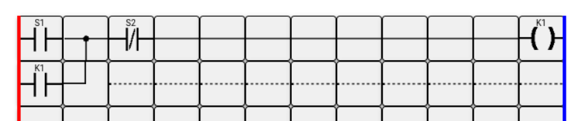
As an example, let us consider an extremely simplified and common contactor control circuit implemented in the LD language.
In the initial state, the contacts of pushbutton S1 are open, and the contacts of pushbutton S2 are closed. Power is not supplied to the contactor coil K1. Contact K1 is open.
When pushbutton S1 (START) is pressed, its contacts close, and the supply voltage passes through the normally closed contacts of pushbutton S2 (STOP) to coil K1. The coil is energized, and contact K1 closes. After releasing the button and opening the contacts of pushbutton S1, the coil continues to receive power through its own contact K1 and the normally closed contacts of pushbutton S2.
When pushbutton S2 (STOP) is pressed, its normally closed contacts open. The coil is de-energized, and contact K1 opens.
At present, the LD programming language is actively used by such leading PLC manufacturers as Modicon, Siemens, Mitsubishi, Toshiba, and others.
Minaev I.G. Programmable Logic Controllers: a practical guide for a beginner engineer. / I.G. Minaev, V.V. Samoilenko. – Stavropol: AGRUS, 2009 – 100 p.