Normally Open Contact

If the diagram contains a coil with the same name as the normally open contact, then the contact is considered to belong to this coil. If the coil is energized, its normally open contact is closed; otherwise, it is open.
Normally Closed Contact

If the diagram contains a coil with the same name as the normally closed contact, then, if the coil is energized, the normally closed contact is open; otherwise, it is closed.
Pulse Counter

The pulse counter counts pulses applied to its input. When the number of pulses matches the value specified in the input field, the output state changes to the opposite state, and the counter starts counting again from zero until the next match.
Pulse Generator

The PULSE generator generates rectangular pulses with an equal duty cycle and has one parameter: the pulse duration in seconds. It also has an input logical level. If the input level is 1, pulse generation occurs; if it is 0, pulse generation stops.
TON Timer

The TON timer. After the time specified in the parameter has elapsed following the application of logic 1 to the input, a high level will appear at the output. If the input level changes back to low before the output level changes, the internal time counter of the component is reset to 0 and the output level does not change.
TOF Timer (off-delay)

The TOF (off-delay) timer. If the input is logic 1, the output is also 1. If the input level changes from 1 to 0, then after the time specified in the parameter has elapsed, the output level will also change from high to low. If logic 1 is applied again to the input before the output transitions to low, the counter is reset and the output does not transition to the low state.
TP Timer

The TP timer. After logic 1 is applied to the input, a high level immediately appears at the output and is maintained for the time specified in the parameter. If the input level changes to low, the output level also changes to low.
RS Flip-Flop


SET and RESET coils of the RS flip-flop. To illustrate the operation of the SET and RESET coils, see Fig. 10.
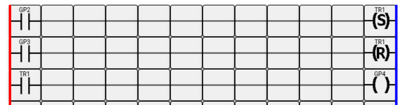
When voltage is applied to controller input GP2, the normally open contact GP2 closes. A high logical level is applied to the SET coil. Provided that there is no voltage on input GP3, the flip-flop is set to 1, the normally open contact named TR1 closes, and accordingly the controller output GP4 is activated.
When voltage is applied to controller input GP3, the normally open contact GP3 closes. A high logical level is applied to the RESET coil. Provided that there is no voltage on input GP2, the flip-flop is reset to 0, the normally open contact named TR1 opens, and accordingly the Raspberry Pi output GP4 is turned off.
If voltage is present simultaneously on inputs GP2 and GP3, the flip-flop retains its previous state.
Similarly, if voltage is absent simultaneously on both inputs, the flip-flop will continue to retain its previous state.
The RS flip-flop is usually used to store in memory a certain event or a certain state of the circuit.
Conductors
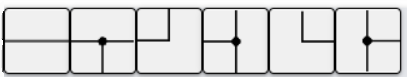
They are used to connect the components of the ladder diagram to each other and to the power supply buses in various combinations.
I recommend following the link to the online editor and experimenting with the components in practice for better understanding.