So, we’re going to turn a low-cost Raspberry Pi Pico board (about $5) into a real programmable logic controller (PLC). And to set up the logic for our homemade PLC, you only need to know how to read electrical schematics.
We can automate things like a greenhouse, a water pump, or automatic gates — it all depends on the logic you design. The only limit is your imagination. The Raspberry Pi becomes the brain that controls everything.What You’ll Need:
What You’ll Need:
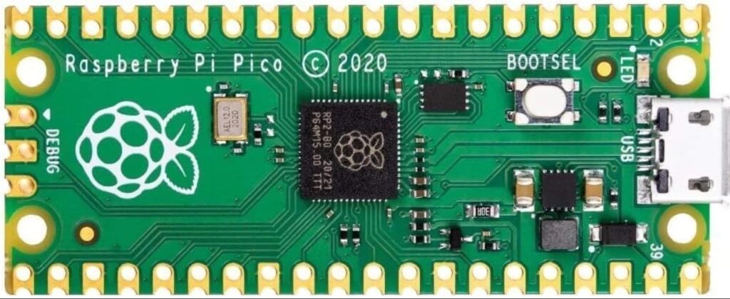
- A Raspberry Pi Pico board — you can buy it in online stores like Amazon, Ebay etc.
- Download the firmware for the Pico: Pico-firmware.uf2 download link
- Connect the board to your computer while holding the BOOTSEL button. It will appear like a USB drive, and then you can copy the firmware file onto it.
Setting Up the Logic:
- Download and install the LAD-Editor program. download link from Yandex Disk
- In LAD-Editor, you draw your electrical schematic using ladder diagrams — these diagrams look like relay-based control circuits, with contacts and coils.
- The logic you draw in the diagram becomes the “program” that runs on the Raspberry Pi. Upload it to the microcontroller — done!
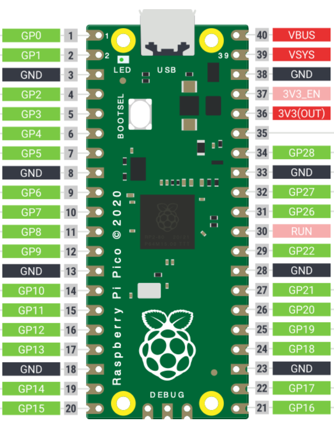
- In the example shown in the diagram, the built-in LED (connected to GP25) will turn on when you apply 3.3 V to the GP1 pin from the 3V3 output. You can test this by connecting these pins with a wire.

Technical Details:
- The programming uses the Ladder Diagram (LD) language, which is part of the IEC 61131-3 standard.
- This language is designed for electrical engineers who may not know languages like C, C++, or Python — but who can read electrical schematics.
- LD is used by well-known PLC manufacturers like: Siemens, Schneider, Omron, Allen-Bradley, and Mitsubishi.
How to Work With LAD-Editor:
- There is a short video , that shows how to use LAD-Editor. (The video uses a different board — ESP8266 — but the principle is the same. Only the pin names differ.)
- You should use the pins marked from GP0 to GP28 (highlighted in green in the diagram). But note: GP25 is used by the built-in LED.
- In the ladder diagram, if a Pico pin is defined as an input (normally open or normally closed contact), that input is considered active when 3.3 V is applied from the 3V3 (OUT) pin.